Lab 1: FPGA and MCU Setup and Testing
Introduction
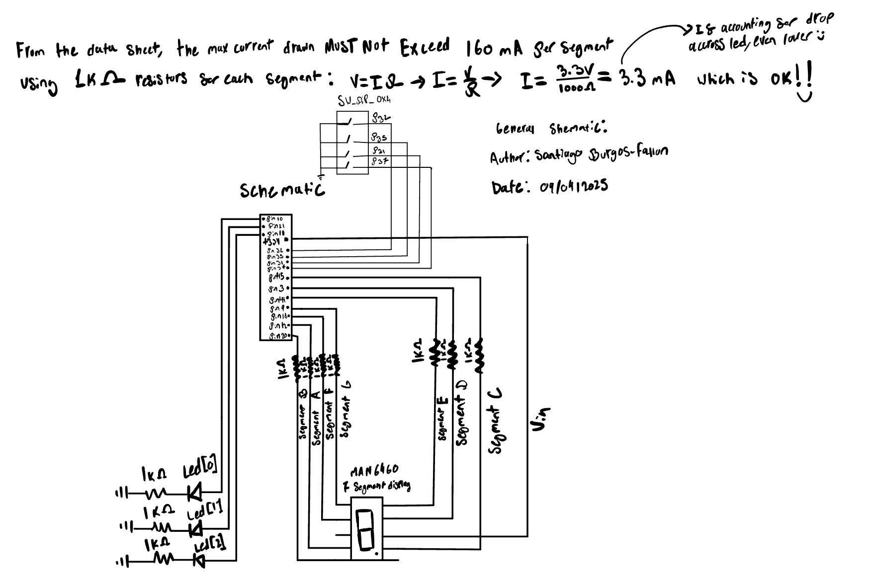
In this lab I assembled the E155 development board, verified power rails, and brought up both the UPduino v3.1 FPGA (iCE40-UP5K) and the Nucleo-L432KC MCU. I then wrote SystemVerilog to (1) drive three LEDs per the given truth tables and (2) decode a 4-bit input from the on-board DIP switches (SW6) to a common-anode 7-segment display. The switches provide s[3:0] directly into the FPGA; the decoder drives seg[6:0] (active-low) through 1k ohm resistors to the display so that the selected hex digit lights correctly. Designs were simulated in QuestaSim, synthesized in Lattice Radiant, and programmed to the UP5K;
Design & Testing Methodology
Architecture
- Internal 48 MHz HSOSC feeds a power-on reset counter and a parameterized divider that creates a ~2.4 Hz tick for
led[2]. led_logicimplements the required LED truth tables and optional active-low polarity.SevenSegis a combinational hex→segments decoder with active-low outputs (for a common-anode display).
![HSOSC to POR and BlinkDiv to led_logic; SevenSeg in parallel from s[3:0].](images/sv.jpg)
sbf_lab1).
Unit tests (simulation)
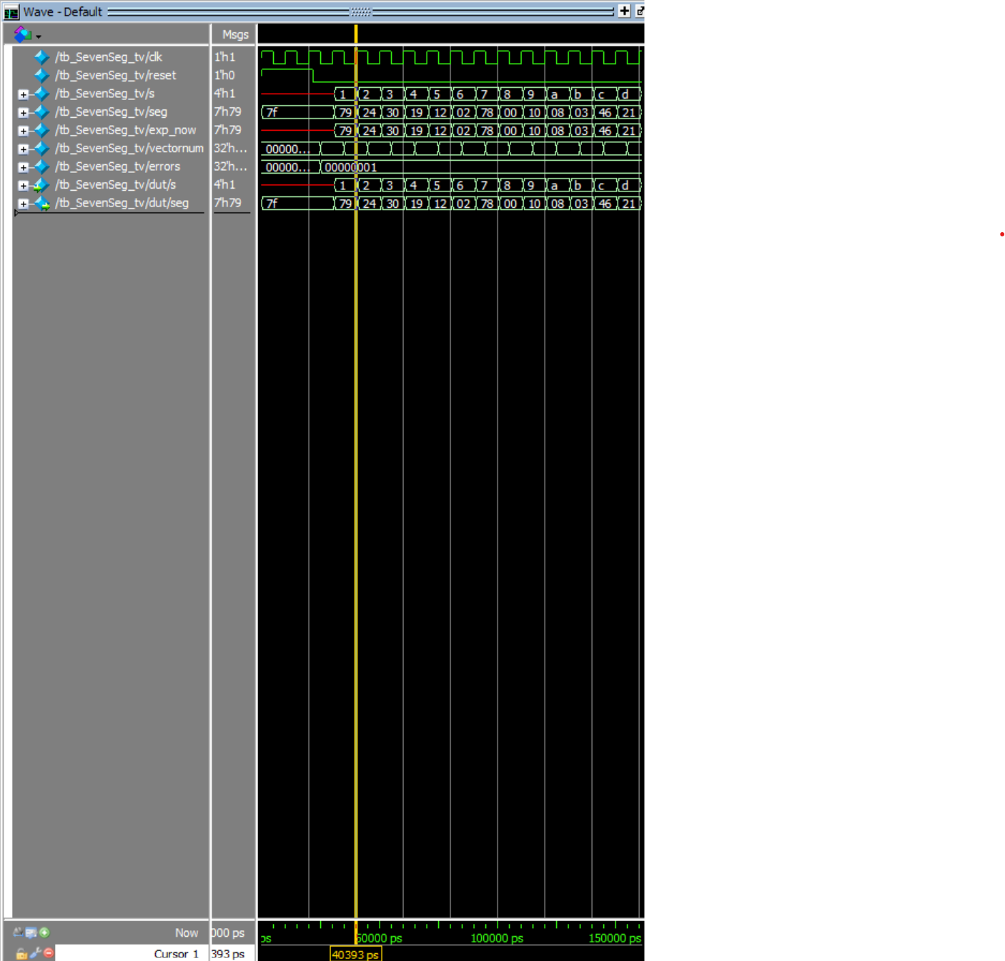
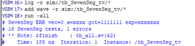
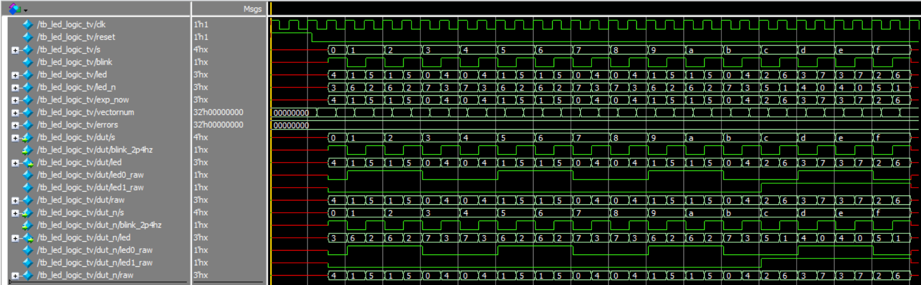
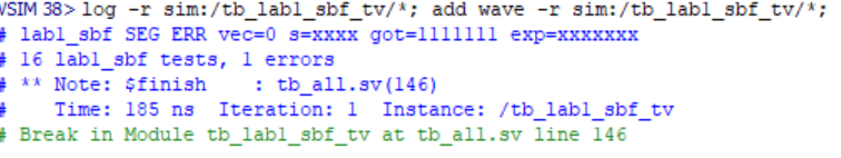
Self-checking testbenches read .tv vectors: - tb_SevenSeg_tv verifies the 0x0–0xF map. - tb_led_logic_tv checks both active-high and active-low instances. - tb_lab1_sbf_tv checks seg and led[1:0] at top level (blink bit ignored).
On the single “error”: one vector intentionally contains unknowns (
xxxxxxx) to represent a “don’t-care” state during initialization. The testbench expectsxxxxxxx, while real hardware (with pull-ups and reset) resolves to1111111(all segments off). Functionally correct; the failure is in the expected vector, not the DUT.
Hardware bring-up
- Verified +5 V and +3.3 V LDO outputs on VIN power before inserting modules.
- Wired one side of the dual 7-segment (common-anode) with series resistors on each segment; anode to 3.3 V.
- Used ~1 kΩ series resistors → ≈3.3 mA/segment (ignoring LED (V_f)), comfortably within limits: [ I = 3.3 ]
Technical Documentation
- Code directory:
https://github.com/s4anti4go/E155/tree/main/FPGA/RadiantProject/Lab%201- FPGA design: `
sbf_lab1(top). - Testbenches:
tb_all.sv.
- FPGA design: `
- Tools: Radiant (synthesis, constraints, Netlist Analyzer), QuestaSim Lattice Edition (simulation), SEGGER Embedded Studio (MCU).
LED behavior specification
| S1 | S0 | led[0] |
|---|---|---|
| 0 | 0 | OFF |
| 0 | 1 | ON |
| 1 | 0 | ON |
| 1 | 1 | OFF |
| S3 | S2 | led[1] |
|---|---|---|
| 0 | 0 | OFF |
| 0 | 1 | OFF |
| 1 | 0 | OFF |
| 1 | 1 | ON |
led[2] blinks at ~2.4 Hz from the divider: \[
\mathrm{TOGGLE\_COUNT}
= \frac{48\,\mathrm{MHz}}{2 \cdot 2.4\,\mathrm{Hz}} - 1
= 10{,}000{,}000 - 1
\]
Seven-segment notes
- Common-anode display → active-low segment lines (
0turns a segment on). - Naming:
seg[0]=A … seg[6]=G. - To turn on correct segments:

Results & Discussion
Seven-segment unit tests
LED logic unit tests

Top-level simulation
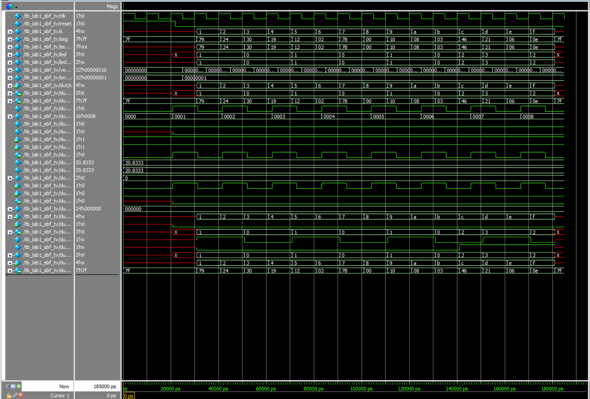
sbf_lab1) QuestaSim waves sweeping s=0..F.
Interpretation.
- led_logic passes all vectors for both polarities.
- SevenSeg and top-level each show one flagged vector where the testbench expects unknowns; hardware resolves to all off (1111111). Functionality is correct; the discrepancy is only in the expected file’s init case.
- Divider math and POR behavior match intent; led[2] toggles at the expected rate (simulation time scaled).
Conclusion
I assembled and powered the E155 dev board, verified MCU↔︎FPGA connectivity, and implemented the required FPGA logic: LED truth tables, a ~2.4 Hz blink, and a combinational 7-segment decoder for a common-anode display. Simulation, synthesis, and on-board testing confirm correct behavior. The lone “failure” in automated tests is a deliberate X-expectation vector that resolves to “all off” in hardware.
Time spent: 20 hours.
All Code https://github.com/s4anti4go/E155/tree/main/FPGA/RadiantProject/Lab%201
AI Implementation
Prompt
Write SystemVerilog HDL to leverage the internal high speed oscillator in the Lattice UP5K FPGA and blink an LED at 2 Hz. Take full advantage of SystemVerilog syntax, for example, using logic instead of wire and reg.
What the LLM produced (Gemini)
Good ideas it used: - Parameterized divider (CLK_FREQ, BLINK_FREQ) with $clog2 sizing - Modern SV constructs (logic, always_ff) - Clear split: top module that wraps an oscillator primitive + a blinker child
Top-level snippet returned (abridged): module led_blink_top (output logic o_led); logic clk_48mhz; SB_HFOSC u_hfosc ( .CLKHFPU(1’b1), .CLKHFEN(1’b1), .CLKHF(clk_48mhz) ); defparam u_hfosc.CLKHF_DIV = “0b00”; // 48 MHz led_blinker u_led_blinker (.clk(clk_48mhz), .led(o_led)); endmodule
Synthesis outcome
Radiant failed at the oscillator instantiation with: VERI-1063: instantiating unknown module SB_HFOSC Root cause: Radiant’s iCE40 UltraPlus technology library expects the HSOSC primitive, not SB_HFOSC (the SB_* form is common in iCEcube2 examples).
Fix applied (works in Radiant): // iCE40UP internal HF oscillator HSOSC #(.CLKHF_DIV(2’b00)) // 00 = 48 MHz hf_osc (.CLKHFPU(1’b1), .CLKHFEN(1’b1), .CLKHF(clk));
I also replaced the LLM’s initial-based register inits with a tiny synchronous power-on reset (POR) counter so hardware powers up in a known state.
Quality rating (and why)
- Rating: B
- Strengths: idiomatic SV, readable, correct divide-by-N math, parameterized for reuse
- Weak spots: vendor primitive mismatch (
SB_HFOSCvsHSOSC),defparamstring style ("0b00"), reliance oninitialfor synthesis reset
What I learned / new constructs
$clog2is handy for auto-sizing counters and synthesizes cleanly on UP5K.- Parameterizing the blink frequency made switching between 2 Hz (prompt) and 2.4 Hz (lab) a one-line change.
Errors & warnings encountered
- Radiant:
VERI-1063 instantiating unknown module SB_HFOSC→ resolved by switching toHSOSC #(.CLKHF_DIV(2'b00))and wiringCLKHFPU/CLKHFEN/CLKHF.
Tips for using LLMs for HDL (next-time playbook)
- Specify tool, family, and exact primitive in the prompt: target Lattice Radiant for iCE40 UltraPlus (UP5K) and instantiate HSOSC (ports
CLKHFPU,CLKHFEN,CLKHF; paramCLKHF_DIV). - Ask for a synthesizable reset: avoid
initial; include a synchronous reset or a small POR counter. - Request a sim-friendly testbench: faster divider + self-check to validate logic quickly.
- Ask for Radiant-specific guidance: prefer Device Constraint Editor notes over generic
.lpf. - Iterate with exact error text: paste Radiant/Questa messages back to the LLM for precise fixes.
Appendix: Figure index
- Block diagram:
hmc-e155-portfolio/labs/Lab1/images/sv.jpg
- Schematic & current calc:
hmc-e155-portfolio/labs/Lab1/images/elec.jpg
- Top-level waves:
hmc-e155-portfolio/labs/Lab1/images/lab test waves.png,hmc-e155-portfolio/labs/Lab1/images/lab vectors.png
- LED unit waves:
hmc-e155-portfolio/labs/Lab1/images/led test waves.png,hmc-e155-portfolio/labs/Lab1/images/led text tests.png
- Seven-seg waves:
hmc-e155-portfolio/labs/Lab1/images/seven seg waves.png,hmc-e155-portfolio/labs/Lab1/images/seven seg tests.png